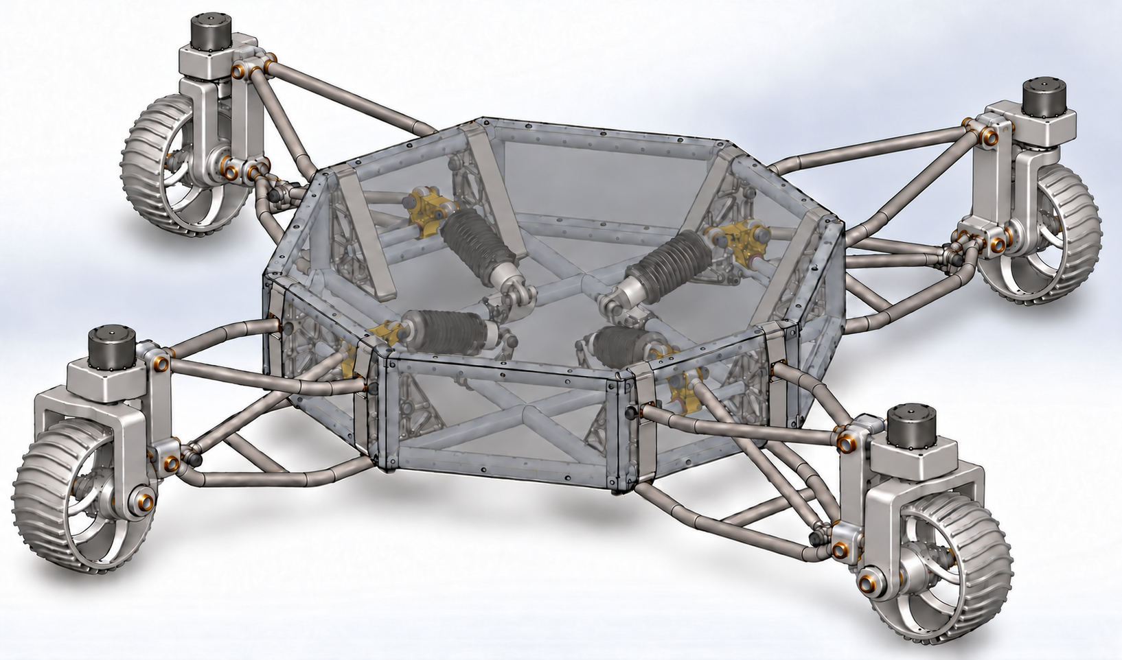
I developed this rover concept to explore a mobility question: can independent swerve steering and long-travel suspension make a rover more maneuverable on uneven terrain and in confined spaces? The work combines chassis CAD, suspension kinematics, wheel-module packaging, basic finite element analysis, and early simulation.
Each of the four wheel modules has independent steering and drive. Coordinating their directions would allow forward travel, lateral translation, and rotation about a chosen center. Double wishbones guide wheel motion, while pushrods and bellcranks transfer that motion to inboard springs and dampers. The mechanical challenge is to preserve steering clearance as the suspension moves, while keeping the spring hardware inside the chassis.
Project status: mechanical design, basic suspension-link FEA, and early simulation. The current rover concept brings together four swerve modules, inboard suspension, and an enclosure around the tubular chassis. I have performed basic FEA on suspension links, and simulation work has reached basic teleoperation. Next priorities are greater autonomy in simulation, edge-case terrain testing, more detailed component and assembly FEA, and design optimization.
Current rover design
The swerve module design took inspiration from Astrolab’s FLEX rover.
The module upright connects to the paired bushings at the outer ends of the upper and lower wishbones through two horizontal revolute mounts. Those pin axes run across the corner-to-center direction, while a separate vertical spindle provides the steering axis. Keeping those interfaces distinct makes the load path from the wheel into the suspension easier to inspect and leaves room to check steering motion independently of suspension travel.
The updated module concept uses a fixed suspension carrier and a separate rotating fork, with a recessed pancake hub motor for direct wheel drive. The azimuth motor, enclosed inline gearbox output, and fork spindle share a vertical steering axis. The intended layout places the fork bridge near the lower suspension link and the wheel axle below the suspension. Straight fork cheeks and a flat bridge form a rectangular window around the wheel, while both fork bearings share its axle. The rear drive housings follow the outward centerlines of their suspension. The illustration repeats the wheel and simplified hub construction at all four corners. Dimensions, bearing selection, joint axes, and clearance through motion still need to be checked in the source CAD.
The wheels are shown as one-piece aluminum parts with an open drum, integral curved spokes, and curved grousers, taking visual cues from Perseverance’s wheels. Each wheel uses one metal color, with its drive motor recessed on the inward face. The full-frame sheet-metal enclosure is shown translucent to keep the original pushrod suspension and spring mounts visible. The illustration focuses on mechanical packaging; electronics and wiring are omitted.
Suspension and packaging
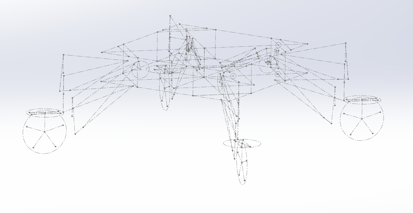
I developed the chassis, suspension, and coaxial swerve modules using master sketches, 3D sketches, and weldments. The original CAD component selections combine an aluminum/steel tube chassis with 7075 aluminum suspension and swerve components, QA1 coilovers with 350 lb/in springs, and AKM42C servomotors. The newer hub-drive packaging shown in the concept visuals is an iteration beyond those original motor selections.

The CAD geometry targets:
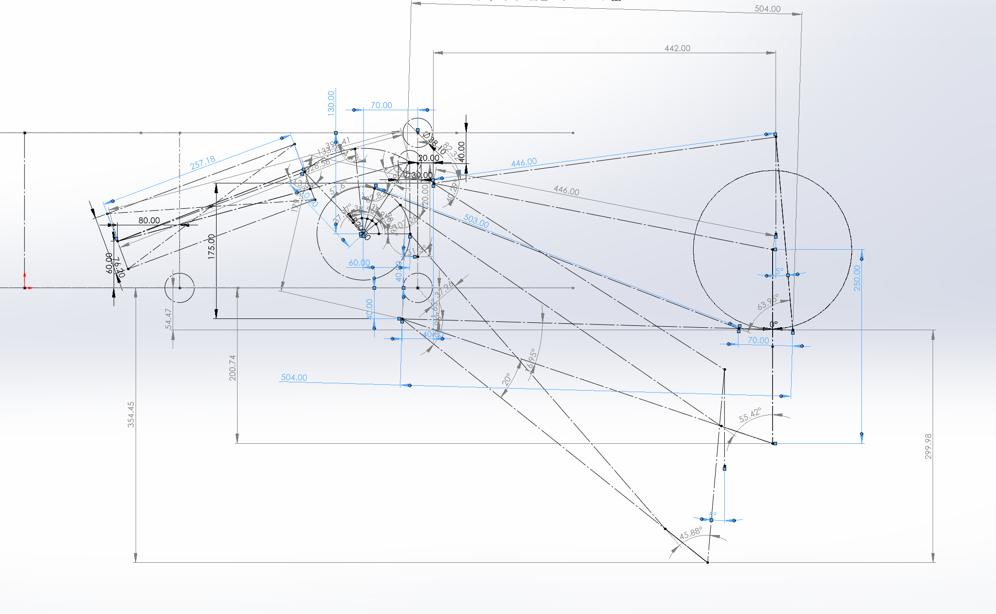
- ±150 mm wheel travel: 300 mm of total design travel for uneven terrain.
- ±5° camber range: a geometry target to examine through the suspension sweep.
- Approximately 500 mm ground clearance: a nominal packaging target, subject to vehicle load and suspension position.
These are design targets rather than measured performance. Locating the springs and dampers inboard is intended to reduce their exposure to the terrain. The pushrod and bellcrank geometry also introduces a motion ratio between wheel travel and spring compression; that ratio must be checked before treating the selected 350 lb/in springs as a suitable wheel-rate choice.
Master geometry coordinates the suspension hardpoints, chassis members, and module interfaces. The next mechanical checks are joint limits, wheel-to-frame clearance through combined steering and suspension motion, and the loads transmitted into the wishbone mounts and rockers.
Future work: autonomy and edge-case environments
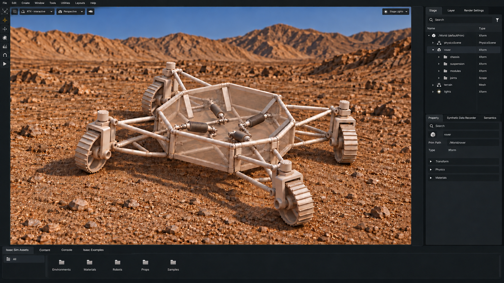
The simulation work has reached basic teleoperation. I plan to develop more autonomous behavior in NVIDIA Isaac Sim, starting with simulated sensor input, terrain mapping, waypoint following, obstacle avoidance, and replanning when a route is blocked. The workflow would use URDF/USD models, ROS 2 controllers, and Isaac Action Graphs to connect perception and navigation to the rover’s drive and steering joints.
The planned simulation work includes:
- Check the imported mechanism. Verify joint axes, limits, collision geometry, mass properties, and linkage motion against the CAD.
- Develop autonomous navigation. Combine terrain mapping with waypoint following and obstacle avoidance, then test route replanning and recovery when progress is blocked.
- Test edge-case environments. Add cross-slopes, unequal wheel heights, low-traction patches, steps near suspension travel limits, and tight passages. These scenes would exercise combined steering and suspension motion beyond nominal flat-ground driving.
- Compare behavior across scenarios. Record path-tracking error, wheel contact and slip, steering error, chassis attitude, and ground clearance under stated terrain and friction conditions.
Simulated RTX LiDAR would support terrain mapping and obstacle detection. I would also vary sensor visibility and traction to examine how navigation responds to incomplete terrain information and difficult wheel contact.
Suspension-link FEA and future optimization
I performed basic SolidWorks FEA on individual suspension links to examine deformation under simplified loads and supports. These component studies are a starting point for more detailed structural analysis as the design develops.
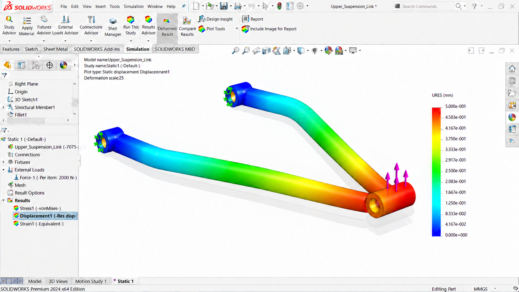
I want to extend the work to more elaborate component studies and assembly-level FEA, including load transfer through the wishbones, pushrods, bellcranks, swerve carriers and forks, and chassis mounts. Assembly studies would examine joint and contact assumptions under vertical and lateral wheel loads, uneven wheel loading, and drive, braking, and steering torques.
I would compare stress, deflection, and factors of safety, with particular attention to holes, pin interfaces, brackets, and changes in section thickness. Mesh convergence and sensitivity to loads and supports would help guide revisions to component thicknesses, fillets, and mounting geometry.
Further down the line, I want to explore topology optimization or parametric design optimization for selected suspension and module components. The aim would be to reduce mass while maintaining stiffness, strength, mounting interfaces, and clearance through motion. Manufacturing constraints would help turn an optimized shape into a practical CAD design.